Motion Fields and Optical Flow
When a camera moves through a scene, each visible 3D point traces a path across the image plane. The motion field is the projection of this 3D motion onto the image: it assigns a 2D velocity to every image point. This post derives the motion field equation and shows what it reveals about scene depth and camera motion.
Setup
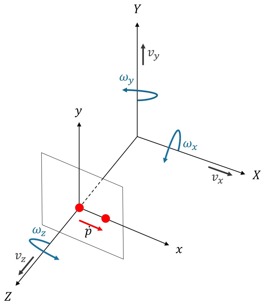
Assume a rigid, static scene and a camera with translational velocity and rotational velocity . A scene point , expressed in the camera frame, projects to the normalized image point :
Derivation
Step 1: Motion of the point. Relative to the camera, a static point moves opposite to the camera’s motion:
Expanding the cross product gives
Step 2: Differentiate the projection. Applying the quotient rule to gives , or in components:
Step 3: Substitute. Inserting the expressions from Step 1 and replacing with and with gives
In matrix form, this is the motion field equation:
Translation and Rotation
The two components behave very differently:
- Translational flow depends on depth. It scales with , so nearby points move faster in the image. This effect is known as motion parallax.
- Rotational flow is independent of depth. does not appear in this term, so a purely rotating camera provides no information about scene structure.
- Scale is ambiguous. Translation and depth appear only as the ratio , so a single camera cannot recover absolute scale from image motion alone.
Special Cases
Setting all but one velocity component to zero isolates the basic flow patterns. The animations below are computed directly from the motion field equation at constant depth, with image pointing right, image pointing down and pointing forward. Reversing a velocity reverses its arrows.
Pure translation. Sideways motion gives uniform flow opposite to the camera, and forward motion gives radial flow:
Pure rotation. Rotation about or gives nearly uniform flow near the image center that curves toward the edges, and rotation about the optical axis gives circular flow:
Near the image center, rotation about and translation along look nearly identical: for small and , and . The same holds for rotation about and translation along , so the two are difficult to separate with a narrow field of view.
Explore the Equation
The explorer below evaluates the motion field equation live. Choose a camera motion and a scene, then move the pointer over the image to read the flow at that point.
- Image center
- (0, 0)
- Depth Z
- 1.0
- Flow
- (0, 0)
- FOE
- (0, 0)
- Time to contact
- 1.7
Two experiments are worth trying. First, select Forward + pan: the rotation hides the direction of travel, and the flow appears to expand from the wrong place. Removing the rotational flow reveals the true FOE, which is why robots estimate and subtract rotation first, often with a gyroscope. Second, select Sideways with Two objects at different depths: the nearer object visibly moves faster, and that difference is the depth signal.
Focus of Expansion
Factoring out of the translational flow gives
This flow is zero at a single image point, and every flow vector points along the line through it. This point is the focus of expansion (FOE), and it marks the camera’s direction of travel:
When , the FOE moves to infinity and the flow vectors become parallel.
Time to Contact
The time to contact is the time remaining before the camera reaches the plane of a point, assuming constant velocity:
Taking the magnitude of the translational flow above and rearranging gives
Notably, time to contact can be measured from a single moving camera without knowing either depth or speed, even though neither can be recovered individually. It requires only the flow vector and its distance from the FOE. Among points at the same distance from the FOE, longer flow vectors therefore indicate a more imminent collision.
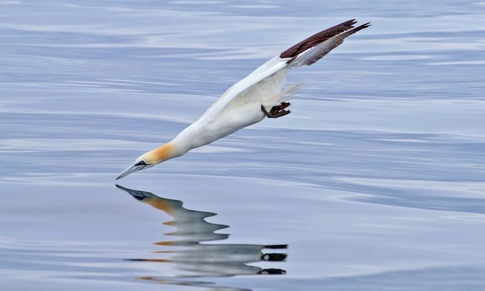
Time to contact is widely used for obstacle avoidance on small robots, and it also appears in nature. Gannets enter the sea like torpedoes: they plunge at high speed and must fold their wings just before impact. Their timing is consistent with a time-to-contact estimate from the expanding image of the water, rather than separate estimates of height and speed [1, 2].
Motion Field vs. Optical Flow
A camera cannot measure the motion field directly. It observes only changing brightness patterns, and the apparent motion of these patterns is called optical flow. Optical flow is an observable approximation of the motion field, but the two are not always equal.
A rotating sphere shows the difference. Both spheres below rotate, so both have the same motion field, but only the textured one produces optical flow. A uniform sphere looks unchanged.
The reverse also occurs. A moving light changes the shading across a stationary sphere and its surroundings, which produces optical flow although the motion field is zero.
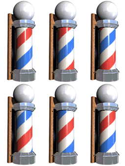
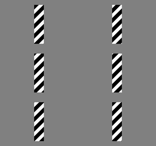
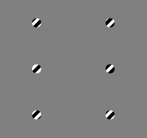
Local measurements add a further ambiguity. Through a small window, only the component of motion perpendicular to an edge can be observed. This is the aperture problem, and it explains why a barber pole’s stripes appear to move vertically although the pole rotates horizontally.
References
- D. N. Lee, “A theory of visual control of braking based on information about time-to-collision,” Perception, 1976.
- D. N. Lee and P. E. Reddish, “Plummeting gannets: a paradigm of ecological optics,” Nature, 1981.